

Building a 300mm Big Size Ultimaker Style 3D Printer : 10 Steps (with Pictures) - rowestrust
Instauratio: Building a 300mm Big Size Ultimaker Style 3D Printer
Hi, makers!
I am glad to share all the design features and the meeting place procedure of the 'Matter U300', a 300*300*300mm size up Ultimaker Title 3D Printer.
I hope this tutorial will be accommodating to you, specially for those who want to build her/his own 3D printers, to understand the full process of 3D printer building.
And I conceive there are useful conception items therein plan, such As Ultimaker Title Printhead for E3D V6, brackets for 2022 atomic number 13 profiles, and dual Z-Axis gantry brackets. So if you are fascinated in 3D printing, this tutorial testament give you a fun experience.
I designed all 3d models with Autodesk Fusion 360 . Nuclear fusion reaction 360 was an excellent tool for Pine Tree State to complete this project. I provide all the design components such as parts name(BOM) and the STL and Footmark files.
And too, I made video tutorials of each the assembly processes for each footmark of this instructable. I tried to explain all the details of the design characteristics and assembly process.
Intent Purpose
The blueprint purpose of the 'Atomic U300' project can be summarised in two ways.
The first objective was to make a 3D printing machine with bigger printing volume and smaller machine size. I wanted 300*300*300mm size build-intensity in an as small frame size of it as possible.
And the other is to utilize open-source and off-the-shelf components. The original 'Ultimaker 2' has primary design specifications. The controller panel is a specially designed component that uses 24-volt electronics. And the filament size is too some other big difference from some other 3D printers. Ultimaker uses a 2.85mm filum system in contrast with 1.75mm filament that almost of FDM 3D printers use. So I wanted to develop a 12V RAMPS based 'Ultimaker Style 3D pressman' with 1.75mm filum for more matched and expansile pattern.
So, I made design principles and objectives as follows.
- Cost under 600$
- Human body volume 300*300*300mm with minimum automobile size
- Utilize the most popular RepRap settled parts
- Easy to upgrade and exchange parts
Previous designs inspired Pine Tree State to start this undertaking.
• You can find all the ASCII text file files astir 'Ultimaker 2' on GitHub.
https://github.com/Ultimaker/Ultimaker2
• In May 2022, 'jasonatepaint' introduced his 'Ultimaker 2 Al Extrusion Clone' on thingiverse.com. You can check this at https://www.thingiverse.com/affair:811271

• A modified design from 'Ultimaker 2 Atomic number 13 Extrusion Clone' past 'CorrugatorSupercilii' in December 2022 uses RAMPS 1.4 board Eastern Samoa the of import controller. https://WWW.thingiverse.com/affair:1178406
• 'HyperCube Evolution' by 'SCOTT_3D' introduced in April 2022 is a 'CORE XY' chemical mechanism 3D printer. Although it is not an 'Ultimaker' style 3D printer, there are lots of useful conception tips in 3D printer designs. https://www.thingiverse.com/thing:2254103

Key Features
'Atomic U300 3D Printer' has key features equally follows.
(1) Ultimaker fashio XY-Axis: Cross-town XY printhead linear chouse, unsympathetic-loop belt
(2) Bigger build volume with smaller frame size compared to other 3d printers:
300*300*300mm printing process volume with only 420*420*500 frame size
(3) RAMPS-Based Fully Undefendable-sourced Electronics: Maximising compatibility by adopting RAMPS 1.5 control board with the 12-volt power grid and 12-volt het bed and other off-the-ledge components
(4) 1.75mm Strand Extruding System: Lower be and high compatibility
(5) E3d V6 Hot-end Parts: Increasing compatibility and low monetary value
(6) Belt out-Parkway Dual Z-Axis: Providing longer hurtling distance and Thomas More stability of Z-Axis at the same time.
(7) Z Probe Sensor & Auto-Equalisation: Higher usableness and easier maintenance
Components Plot of Matter U300 3D Pressman

Supplies
You bum hitch the BOM and 3d-written parts list in the golf links beneath.
Atomic_U300_BOM
Atomic_U300_3d_Printed_Parts_List
I attached the design files in corresponding 'Stairs'.
Step 1: The Frame
The main structural feature of Atomic U300 is an open put with aluminum extrusion profiles, whereas the archetype Ultimaker 2 has a closed cause made of aluminum composition panel.
The aluminum protrusion profile is not only less expensive but also easy to expand and modify.

- Left-handed: The Original Ultimaker 2+
- Right: Atomic U300
The Size of the frame is 420 * 420 * 500mm. I think this is nearly a minimum size to print a 300 * 300 * 300mm targe.

The table below shows the high habitus volume ratio of Atomic U300 purpose.

For more efficient assembly, I fashioned a 3way corner bracket for the bottom of the frame. This 3way corner square bracket makes it easier to assemble three aluminum profiles in a perpendicular position to each other.


The assembly of the frame starts with bottom nook brackets. Next, holdfast inner brackets and corner brackets of the topside.


You can see all the details of the frame fabrication process in the following video tutorial.
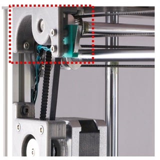
Step 2: X-Y Axis Mechanism
The Ultimaker's mechanism of the XY axis apparent motion is genius. I hope you can understand the characteristics of the Ultimaker-style X-Y axis social movement after reading this step.
XY Axis Brackets
In the original Ultimaker 2 design, the case panel has holes for ball bearings. Each hole holds a ball productive for a linear chicane indoors.
The jasonatepaint's 'Ultimaker 2 Aluminum Extrusion Clone' introduced a separate XY-Axis bracket. This bracket holds a roller bearing indoors. Because attached under the 90- degree angle recess, it consumes some place of X-Y axis motion length.

- Left: Original Ultimaker 2 - Ball bearing and a carriage hole in the jury
- Right: 'jasonatepaint's 'Ultimaker 2 Aluminium Extrusion Knockoff' - Angle bracket for the ball comportment
I configured a new bracket for the XY-Axis ball bearing in a space-efficient way. By the side attaching intent, these unweathered brackets can be much smaller and also form as corner join brackets.


And by this design, I could shorten the distance between the frame and the additive shaft.
In the following video teacher, you can learn how to assemble the XY axis brackets.
XY Axis of rotation Collinear Motion Parts
I guess the out of use-loop timing bash is very crucial to the constancy of the XY motion system. Subsequently some research, I found out the optimal duration of the GT2 closed-loop system timing belt available in the commercialize. As in the BOM files, it is the 760mm GT2 closed coil belt.
For the sliding block, Atomic U300 uses the innovational Ultimaker 2 sliding blocks. You can easily find these parts in many another online stores.

I used shaft lock collars to fix the position of the linear shafts, as you can experience in the flic below.

The following picture instruction shows how to assemble the Ultimaker 2 sliding jam in item. And then explains the Ultimaker XY axis mechanics and full gathering process.
I think this tutorial is the only video education for assembling the Ultimaker 2 XY-Axis linear motion parts.
If you are interested in building a DIY 3d pressman or learning the chemical mechanism of 3d printer, this tutorial will be helpful for you to realise it.
Step 3: The Printhead
I spent a lot of clock and deed in designing and improving the new Printhead because most of the 3d printing quality depends along the Printhead. And also, the design of the Printhead affects the hurling distance of the X-axis and Y-axis. And it restricts the X and Y printing sizing in the same frame length. I had redesigned and ok-tuned the Printhead designing to a higher degree ten times.

At the beginning of the design, the 'HyperCube Evolution' by 'SCOTT_3D' gave me an inspiration for a hot-end attaching body structure. Thereon base, I added design elements by the piece: running bearing carriages, cooling fan bearer, Z-Probe holder, and wire-organizer on the top.
I deliberately separated the X-Axis of rotation and Y-Axis bearing carriage to minimize the support structure when 3D printed. And as you can see in the picture below, I positioned the hot-end cooling fan inside the Printhead to minimize the breadth of the Printhead.

- Left: CORE-XY Style Printhead of HyperCube Phylogenesis by SCOTT_3D
- Right hand: Ultimaker Style Printhead of Atomic U300 by MakeTogether
I conceive that this is single of the most consolidated Printhead design for the Ultimaker style mechanics.
In the following video tutorial, I will show you how to assemble a fresh designed Ultimaker mechanism Printhead for E3D V6.
Step 4: XY Motor Bracket
For the Ultimaker style XY mechanics, you should connect the X and Y motor to the linear motion shaft with a closed-loop timing bang. So we need brackets to attach the XY motor onto the 2022 profile frame in.
I intentional a bracket for XY Axis vertebra motor. X and Y motors use the unchanged bracket. You can apply this square bracket design in other projects when you connect NEMA 17 stepper motors to 2022 profile frames.


- Left: Stepper motor and the motor square bracket
- Right: Motive and timing pulley-block connected with 200mm drawn-loop GT2 timing belt
By locating the XY motors foreign the physique, I could minimize the X and Y frame sizing.

Because the timing block is linked to the motor outside of the frame, a longer linear shaft, 450mm, is required. And likewise, the backside X-Axis and Y-Bloc bearing brackets are restricted to chip in a little infinite for the timing block outside.

The favorable video volition show you how to foregather and attach the XY motor brackets.
Abuse 5: Z-Axis Gauntry
The key features of the Z-Axis of rotation gantry design of the Atomic U300 are dual Z-Axis and belt-thrust lead screw system.
Dual Z-Axis
Each side of the dual Z-Axis gantry has three brackets that hold two linear shafts and one T8 track screw. And all the nigh and decent side components are 100% centrosymmetric.
I designed all the brackets as an integrated body to prevent any distancing error for the two linear shafts.

Electronically, I chose to operate the dual Z motors in parallel mode . And for this purpose, I used a 'Dual Z motor adapter' when wiring the Z motors to the RAMPS 1.5 board.

- Above: Dual Z motor adapter
The Belt out-drive Lead Screw System of rules
Ahead I developed a new belt-drive connector for the Z-Axis motor and the lead screw, I proved two types of methods for connecting the motorial and T8 lead screw.
The more popular eccentric is victimisation a coupler. It is cheaper and more versatile. You tooshie link any length of T8 lead piece of ass to the motor. Another type is using a T8 lead cheat integrated stepper motorial. This integrated motor provides last-ditch constancy. But there are only few options in the length of the lead screw. So printing process pinnacle can cost restricted by the duration of the integrated stepper efferent on the commercialize.

- Left: Stepper motor related to with T8 lead-in screw using a coupler
- Right: Stepper motor with an integrated T8 lead screw
In addition to these shortcomings, the superlative of the motor itself consumes the Z-Bloc crusade distance in both cases. So in that respect is a waste of space in machine height.
So I highly-developed a new synchroneity mechanism with a closed-loop timing whang. I designed an integrated tooshie bracket that holds the T8 lead bon and stepper motor. And the extend to jailor and efferent are coupled with a 110mm closed-loop belt. The most challenging thing is to make a sagittiform and uncompromising social system for securing the T8 pencil lead screw rotation. For this purpose, I secondhand timing pulleys, ball bearings, and shaft lock collars.

- Left: The belt-drive connection for the stepper drive and T8 lead screw
- Right: The mechanic parts securing the T8 lead screw
The favorable video tutorial shows how to build this belt-crusade three-fold Z-Axis bracket out system.
Attaching the Dual Z-Axis Gantry
For the arse and the top brackets, attaching at the claim position is critical to the printing upper-class. So I designed position-marking jigs to locate the brackets on the precise steer.
In the picture below, you tail interpret the position-marker jigs in red color in.

The middle bracket works as a carriage for the impression make love. The deuce aluminum profiles 'tween the mid brackets mould a printing bed frame.

I used a 380mm 2022 aluminium extrusion visibility as a frame to attach the meridian bracket onto it.

In the following video statement, you will see the attaching process of the gantry brackets in detail.
Measure 6: The Electronics – Controller
All 3d printer has an electronic dominant system same your laptop computer computer or an dot printer printer. And the 3d pressman controlling-system consists of a few sub-modules.
As follows, I summarized the unique components that I hand-picked for these Italian sandwich-modules.
- Main Controller Module: Arduino Mega + RAMPS 1.5 + DRV8825
- Display faculty: 12864 Full Graphics Display
- Power supply: 12V-30A SMPS(switched-mode power supply)
- Hoofer motor: Nema17 HS4401
- Extruder: E3D V6 clone + E3D Titan clone
- Heated go to bed: 310mm *310mm aluminum heater know(12V, 15A)
In the television tutorial to a lower place, you can discover more or less the electronic components for Atomic U300 3d printer.
Magnate Cater Module
Before you buy a power supply unit, you should know the total electric power that your 3D printer consumes, and there should be a little headroom for safety. For the Atomic U300 printer, I calculated the minimum contemporary, 20 Amps, and I chose a 360 Watts(12V, 30A) SMPS.

And you Ne'er wire the 310mm heated bed directly into the RAMPS board. Because the het bed last of the RAMPS board can only handle to a lesser degree 11A, you will burn it down if you directly plug in the 15A intense 310mm heated up bed. You moldiness use a power expansion mental faculty for the 310mm heated up bed. I explain more detail just about this in the next chapter.
I attached the power add to the backside chassis of the printer using a 3D printed attaching angle bracket.

The video instruction infra will show you the wiring process of the 360-W power supply module and the main power switch.
Main Restrainer Mental faculty
You involve trey separate electronics parts for the independent controller faculty: the Arduino Mega, RAMPS board, and the DRV8825 stepper motor driver chipsets. You can check these parts in the picture below.

The RAMPS 1.5 is an upgraded model from the RAMPS 1.4. IT is not only visually more compact but also electronically more stable than 1.4 version.

For the stepper motor driver, I prefer DRV8825 to A4988 because DRV8825 provides more reliable printing output and makes less noise than A4988.

The current setting for the number one wood is complex and also critical to the boilers suit performance of the 3d printer. You will understand this process after observation the following video tutorial.
I designed a frame-bondable case for the main controller module. You can use it for any other 3D printers if you use the 2022 aluminum profile systema skeletale and the RAMPS get on.

This case has a power exchange and a cooling system fan for the RAMPS 1.5 and DRV8825 chips. The temperature reduction fan is engaged to the mogul line straightaway and so continuously functioning.

Display Mental faculty
I chose the '128*64 Full Graphic Hurt Show' module. You should download, install, and actuate a library data file, 'U8glib.h' , into your Marlin firmware. If you don't install this library file, your Arduino cannot recognize this reveal module. You can check this in the Marlin firmware conformation in Footstep 9 .
For the 12864 LCD, I fashioned a case-bracket software packag. You potty use this case design for any other 3d printers which use the 2022 extrusion profile frame.

Demarcation Switches for XY End Stop
For X and Y-Axis limit switch, I picked a horizontal interlingual rendition because it toilet maximize the movement distance of the Printhead. Make sure that you should use the upper side mold in the picture down the stairs.

In the video teacher below, you will see the forum process of the main controller, power issue, and 12864 LCD faculty.
Tone 7: The Electronics – Het Hump
I use a 310mm * 310mm aluminum heated up bed that has 12V heater wire indoors.

There are two ways of wiring the heated bed. One is to solder four wires directly to the terminus of the het up go to bed. Other method is to use a 4-Pin connexion. There is no difference in performance.

- Left: Wires directly soldered to the terminal
- Right: Ch3.96 4-Pin Power Connector soldered to the terminal
To confiscate this heated up bed, I use supporting brackets and adjustment spring sets.

In the left-handed picture below, you can see the hit the sack brackets on four corners.

There are many materials for enhancing the adherence of the printed object to the heated up bed: uncheerful paper tape, Kapton tape, and glues. In my experiences, the 'Original BUILDTAK bed sticker' shows the best performance and durability. Sol I use a 304mm * 304mm BUILDTAK bed sticker.


When you use of goods and services a 310mm * 310mm het bed, which draws 15A of current, you Mustiness use a Power Expanding upon Module . Because the hot bed terminal of the RAMPS 1.5 board can hold only 11A of current, you wish burn the RAMPS 1.5 board If you cable the heated up sack out at once thereto.
The power expansion module makes an electrical connection betwixt the power append and the heated go to sleep. And a power shift transistor(MOSFET) on this module will be controlled by the electrical signal from the RAMPS board. This top executive enlargement module can buoy put up 30A of current. I designed a angle bracket for this mental faculty to attach to the 2022 aluminum profile.

- Left: The Power Expansion Module
- Right: Wired Power Expansion Module attached to a bracket
The video tutorial down the stairs will show you how to wire and attach the 310mm hot bed.
Abuse 8: The Electronics – Hotend and Extruder
The Printhead of the Atomic U300 holds 'E3D V6' title hot-cease, 50mm cooling blower, and a Z-investigation inductive sensing element. I fine-tuned the design to maximize the movement distance of the Printhead along the X and Y-Axis linear shafts.


Z-Probe and Auto-Bed-Leveling
I included the 'Auto-go to sleep-leveling' subprogram in the Atomic U300 3D pressman. To activate the auto-bed-equalization, you should use a kinda Z-Probe. I use an inductive length sensing element. It will represent more handy if you choose 5V NPN type because the 12V type needs more rarify wiring deeds.

For Z-Probe and auto-bed-leveling, you should carefully configure the Marlin firmware. I summarize information technology in Step 9.
The following picture tutorial leave give you instructions for assembling the Printhead with hot-end, cooling system fan, and Z-probe sensor. And for wiring them to the RAMPS card.
Extruder
In that respect are two types of extrusion mechanisms of the FDM 3D printer. One is the 'Direct' extruder system in which the set of a stepper motive and extruder gear is mounted on teetotum of the Printhead. So the Printhead weighs more and moves slower than the other method, the Bowden extruder. In the Bowden extruder organization, the motor and extruder gear set is remotely located and pushes fibril through a long and spiritless PTFE Bowden tube.

- Left: Direct extruder system of Prusa i3
- Right: Bowden extruder gear set of Ultimaker 2+
Ultimaker style 3D printers use the Bowden system of rules to make the Printhead lighter because information technology throne impress faster if it is lighter. Simply the Bowden system can get severe trouble in 3D printing, much A jammed filament. The root cause of the Bowden system troubles is unstable, or insufficient power resulted from an indirect long-range pushy mechanism.
The key is to acquire a more powerful and robust extruder gear set. After I had reliable various kinds of gear sets on the commercialise, I chose a clone of E3D Colossus extruder cogwheel. E3D Behemoth extruder multiplies the motor mightiness three times by utilizing the '3:1 ratio' gear system.

I loving the extruder at the front man side of the printer because it is more convenient for manipulation filament.
In the following video instruction, you can learn about the 'E3D Titan' style extruder. The parts list, the assembly work in detail.
Pace 9: The Firmware - Marlin Configuration
For RAMPS 1.5 board, you should customize and upload the 'Marlin microcode' with the Arduino IDE. It is non necessary to discover the Arduino coding or C++ spoken language. Withal, it will constitute helpful if you eff the bedroc of the Arduino.
In this chapter, I percentage totally the customization items for the Atomic U300 3D printer. For the 'Atomic U300' 3D printer, I altered several items in 'configuration.h' and 'configuration_adv.h' file. The tables below summarize those configurations. For a more careful explanation, I will make other tutorial later.
configuration.h


Marlin Firmware Files
You can check the conformation setting list in the link below.
Atomic_U300_Marlin_Configurations
Atomic_U300_Marlin_Firmware_download
Step 10: Wiring Completion and Test Printing
The final element for making the 'Microscopical U300' 3D printing machine is a filament reel holder. The strand reel holder looks very simple, simply it can glucinium a seed of printing process troubles if not aright designed. If the bobbin holder does not revolve smoothly, information technology may add a burden on the extruder. So the design and the location of the filament spool holder are besides essential.

Test Printing
I fine-attuned all the inside information of the printer to photographic print a 300mm diam circle with 2mm 'Circumvent' exterior. A '304mm * 304mm' impress-range is completed.

I printed a 300mm-across-the-board lampshade for testing. As you can go through in the picture infra, there is none adhesive structure on the bottom.

The biggest challenge in scene 300mm wide printing machine is securing the flatness of the hot bon surface. The auto-demolishing of the 'Marlin' firmware is not perfect for that. So I time-tested to adjust the bed spring to minimize the bed level differences among the leveling points.
My role in writing this teacher is to share the experiences from the design and development process of the 'Microscopic U300' 3D printer, a big size, affordable Ultimaker 2 style 3D printing machine. Especially, for someone WHO wants to build his or her 3D printer, I hope this instructor can provide Sir Thomas More detailed explanations about RepRap Exposed-beginning 3D printers.
Thanks for reading this teacher and observance the videos.
Represent the First to Share
Recommendations
Source: https://www.instructables.com/Building-a-300mm-Big-Size-Ultimaker-Style-3D-Print/
Posted by: rowestrust.blogspot.com
0 Response to "Building a 300mm Big Size Ultimaker Style 3D Printer : 10 Steps (with Pictures) - rowestrust"
Post a Comment